
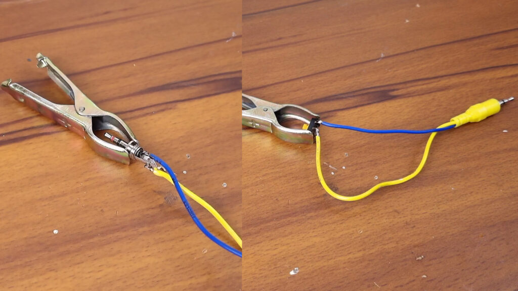
Yes, it is possible to use a remote control with DSLR cameras! Basically, for that, we have two options. Either we buy a dedicated remote by investing quite a bit of money or we can connect a 2.5 mm jack in the shutter trigger port and connect a tactile push switch between the wires shown in the diagram.
Yes, this way, we could use the camera shutter externally but not wirelessly. So, how it would be if we can use the shutter with just a TV remote?! It’s pretty awesome, right? Well, let’s design a circuit that could be triggered with a button press of any IR remote aka Infrared remote.
How Does External Shutter Button Work?
Well, it follows a simple principle. The camera provides a 3.3V and GND throughout the port. If we pull the 3.3V to GND, the microcontroller inside the camera detects it and goes through the codes that are triggered when a camera’s own shutter button is pressed.

Obviously, just like the camera’s shutter button, the external shutter works similarly. After pressing and holding the tactile push switch, the camera first focuses on a particular object, and then it will take a photo. When you hear the shutter sound then you can relax the switch.
Basics of IR Remote
IR remote aka Infrared remote which basically sends data throughout the Infrared light. Depending upon which button you press on an IR remote, it pretty much generates different information; specifically different sets of 0 and 1.
Then according to that information, the IR led blinks and sends the signal to the IR receiver. Here we have nothing to do with that information rather we just have to somehow short the camera’s 3.3V rail to GND with any button press of any remote.
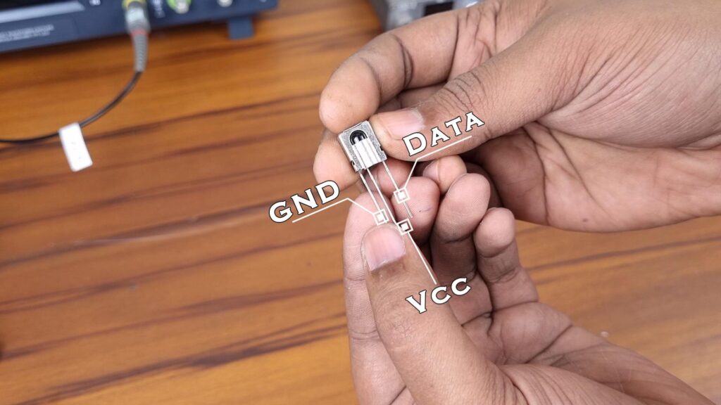
To receive an IR signal from an IR remote, we need an IR receiver. I am going to use this rather cheap one: TSOP1738. It has only 3 pins to work with: GND, VCC, and data out.
How to Use an IR Receiver?
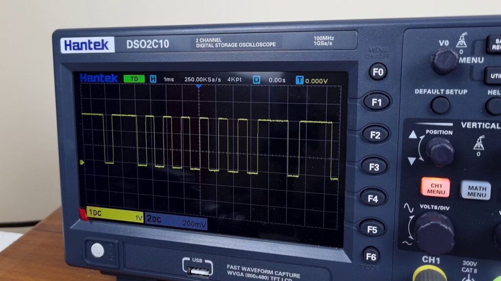
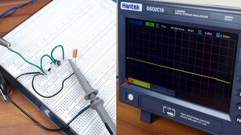
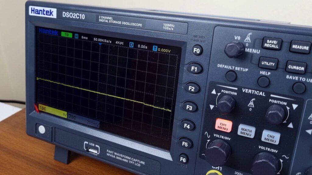
After connecting the VCC and GND of the TSOP1738 receiver with a 3.3V supply, I have hooked up my oscilloscope with its output and immediately found that there is a continuous 3.3V signal.
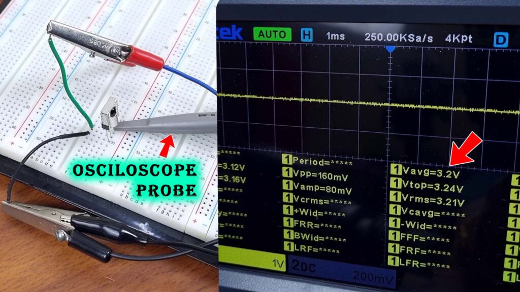
It’s pretty strange but with a proper IR input, the output signal falls back to the ground with every pulse of the signal. This sequence of burst and pause tells so many things. Anyway, we will filter all of this information later. We basically want a neat and clean DC straight-line signal that could only be ‘High’ or ‘Low’ with every button pressed from the remote.
Must Read: Arduino Remote Control Switch: On/Off Room Light With TV Remote
Let’s Design the Circuit to use the DSLR Remotely
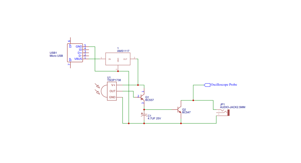
So, first, we have to flip the output state of the IR Receiver. Without proper IR input, the output should be at 0v, and with a button-press from the remote, it could be nearly at 3.3V. This simple state changing is easily possible with a transistor and in this case, I am going with a bc557 PNP transistor.
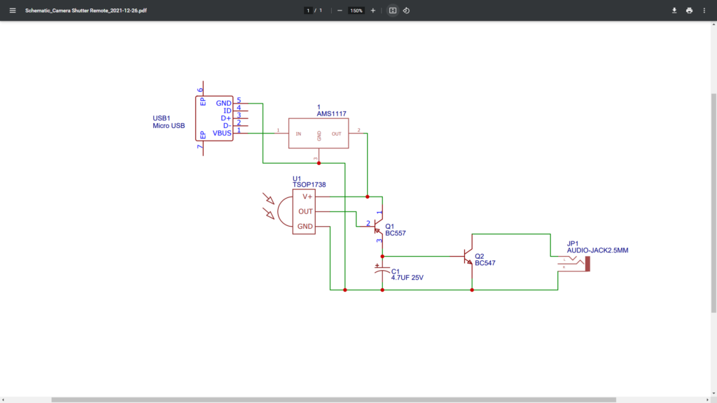
After adding the transistor as shown in the schematic above, the output signal looks like this but with lots of data coming from the remote. Lots of 0 and 1 are coming from certain intervals. We here don’t need that information rather we need only two states of this signal. If a button is pushed then the output signal should be nearly at the supply voltage and without the button press, it should pull back to the GND.
So, to filter out the data, I am going to use a 4.7uf capacity in parallel with the out output of the transistor.
Let’s Short the 3.3V of the camera to Ground Electrically
Now we have got what we need. But we can’t use this signal directly into the camera as I don’t want to take any risk so I am picking up a BJT NPN transistor which will be used to short the 3.3v rail of the camera to GND and the transistor will be triggered with the signal of the remote. So the Collector of the transistor is set with the GND of the circuit and the base is connected with the output of the BC557. The emitter will be connected with the 3.3V rail of the camera and the Camera GND will be connected to GND.

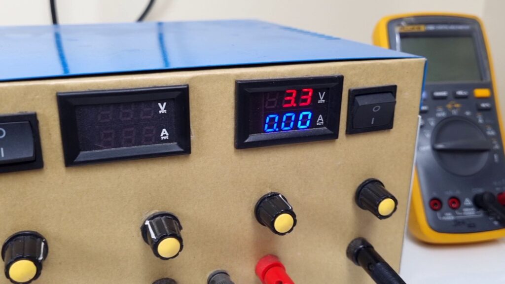
Before powering the testing rig, make sure the power supply is set to a 3.3V supply to avoid any destruction.
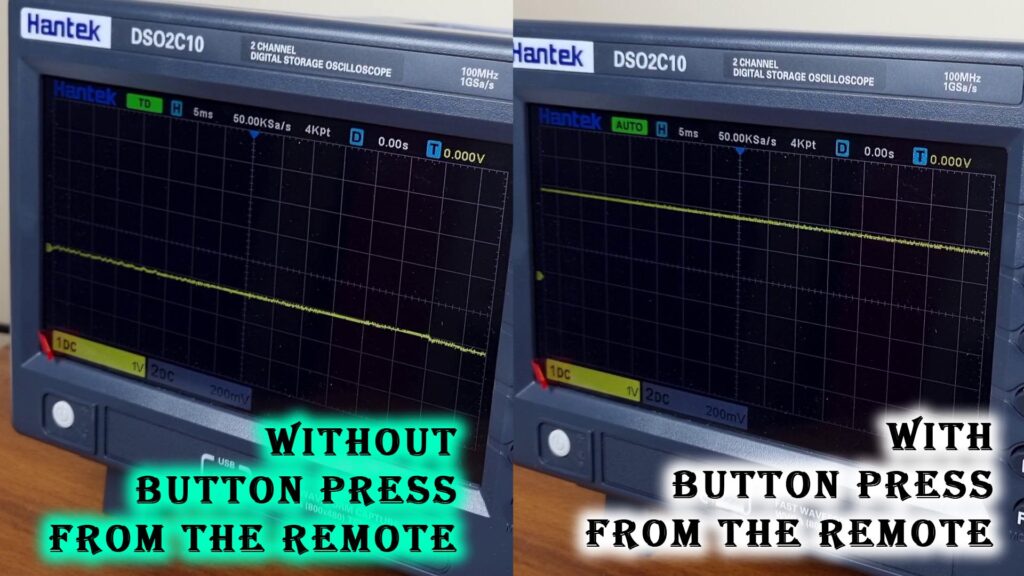
After powering things up, I have hooked my oscilloscope probes with the emitter and Collector pins and immediately found that now the 3.3V rail of the camera is pulled to high, and with a button press, it pulled down to low.
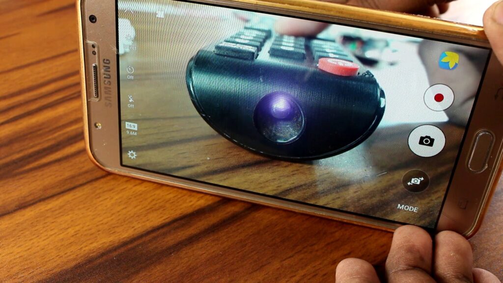
By holding the remote button for a couple of seconds, the camera first focuses on an object and then clicks a photo. Everything is working fine just as we expected.
Let’s Make a rigid Connection between all the components
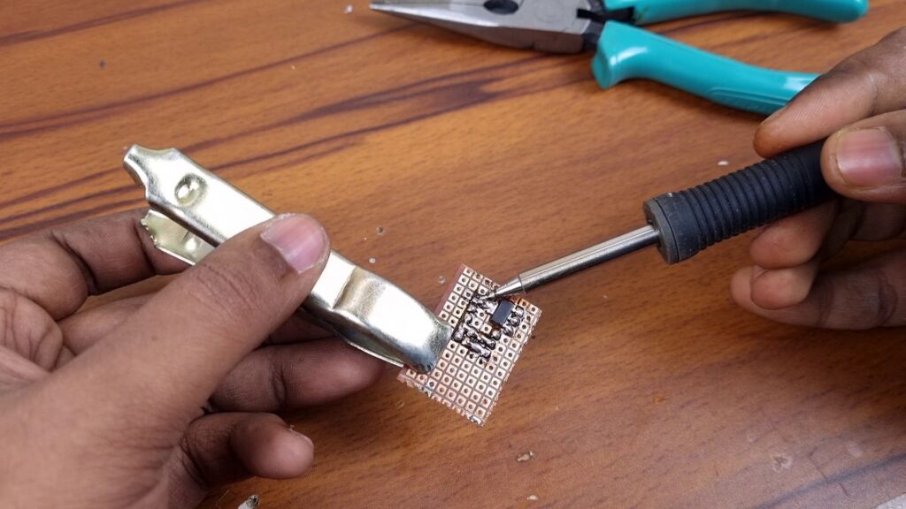
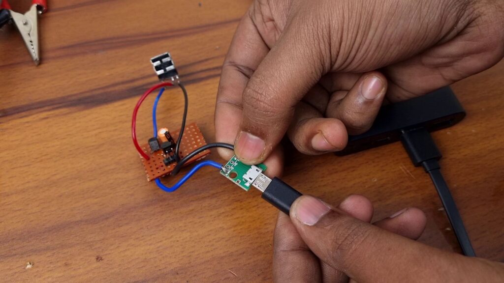
So, to make this circuit permanent, I have soldered all the components on a piece of proof board and for safety, I have used AES1117 3.3V regulator at the voltage input of the circuit and connected micro USB header with the circuit to power it up from a power bank which is still powering my whole camera.
Read Now: Power Your DSLR Camera from Power Bank
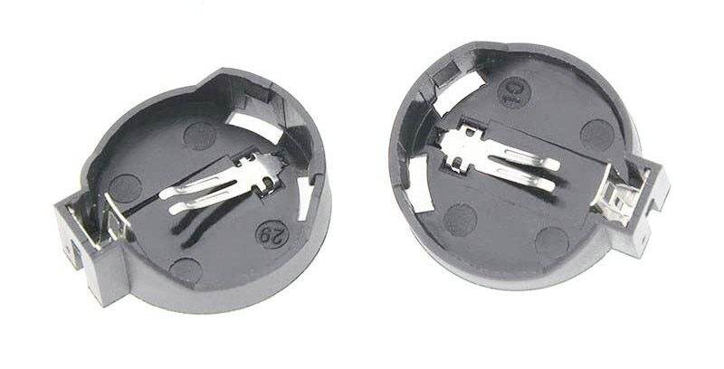
You can though set a CR2032 SOCKET for the respective battery to power the circuit. In that case, you don’t need the regulator.
Enclosing the Circuit & Attach Everything on Top of the Camera
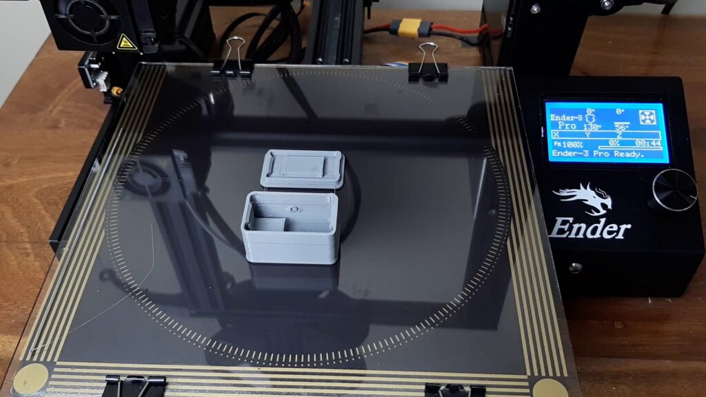
Now we need a small enclosure to pack everything together. So I have measured all the components and designed a case in Fusion 360 and then I have sliced it and print it with my 3D printer.
After removing all the support, I have started placing the components one by one. Started from the micro USB port, next, the IR receiver with the help of a bit of hot glue. And last but not the least, the wire that will be used to connect this receiver to the camera.
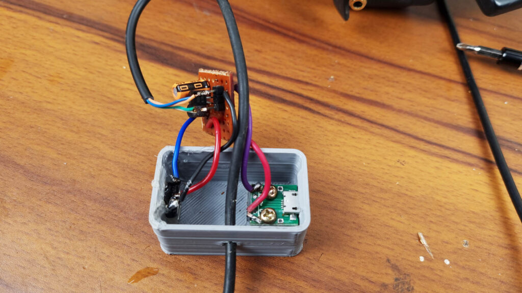
After soldering all the components together as shown in the diagram, I have started assembling the hot shoe mount with the lid of this enclosure.
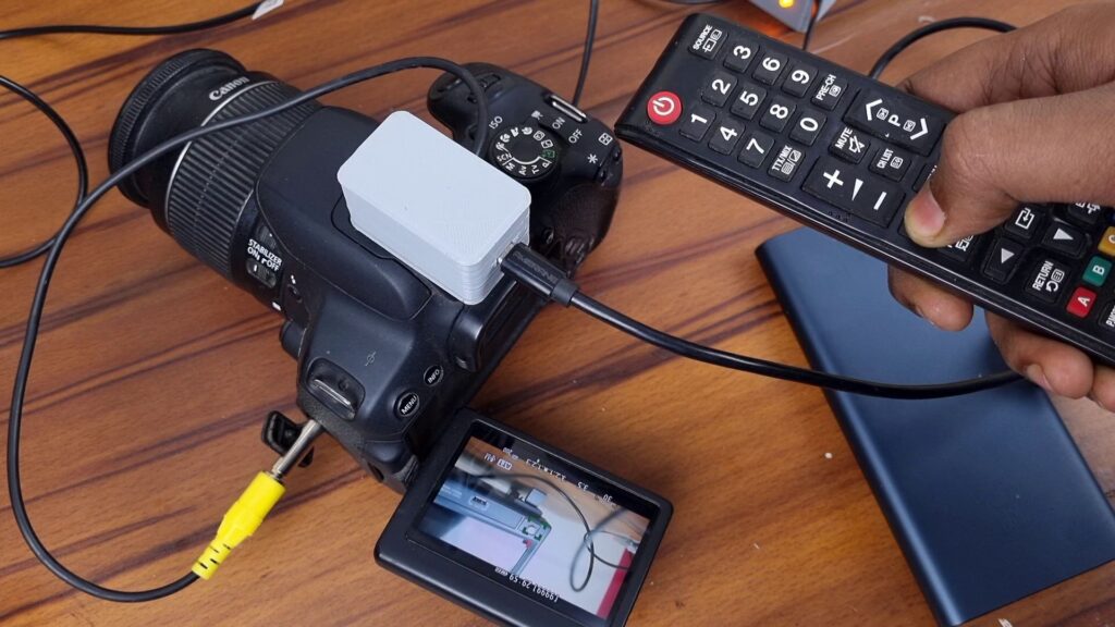
Anyway, After placing all the components inside the body, closing the lid, and inserting the micro USB port into the slot of the other end to the power bank and we are almost ready to shoot but before that, I have mounted this enclosure on top of the cameras hot shoe mount by facing the IR Receiver like this.
Watch The Full Video If You’re Facing Problem:
So, is it a Good Alternative to a Commercial Camera Remote?
Well, Yes but this DIY version is definitely a bit bulky and has to be attached on top of the camera’s hot shoe mount. Commercial solution on the other hand doesn’t need any extra attachment. All the components that need to receive a specific signal from a remote are already integrated into the camera.
By the way, everything is working just fine as we expected. After pressing the remote button for a certain time, the camera focuses on the object and by pressing it a bit longer, it shoots the photo. Hope you guys have learned quite a bit about IR Receiver and remotes. If so then don’t forget to comment down below to appreciate our work. Thanks for visiting.