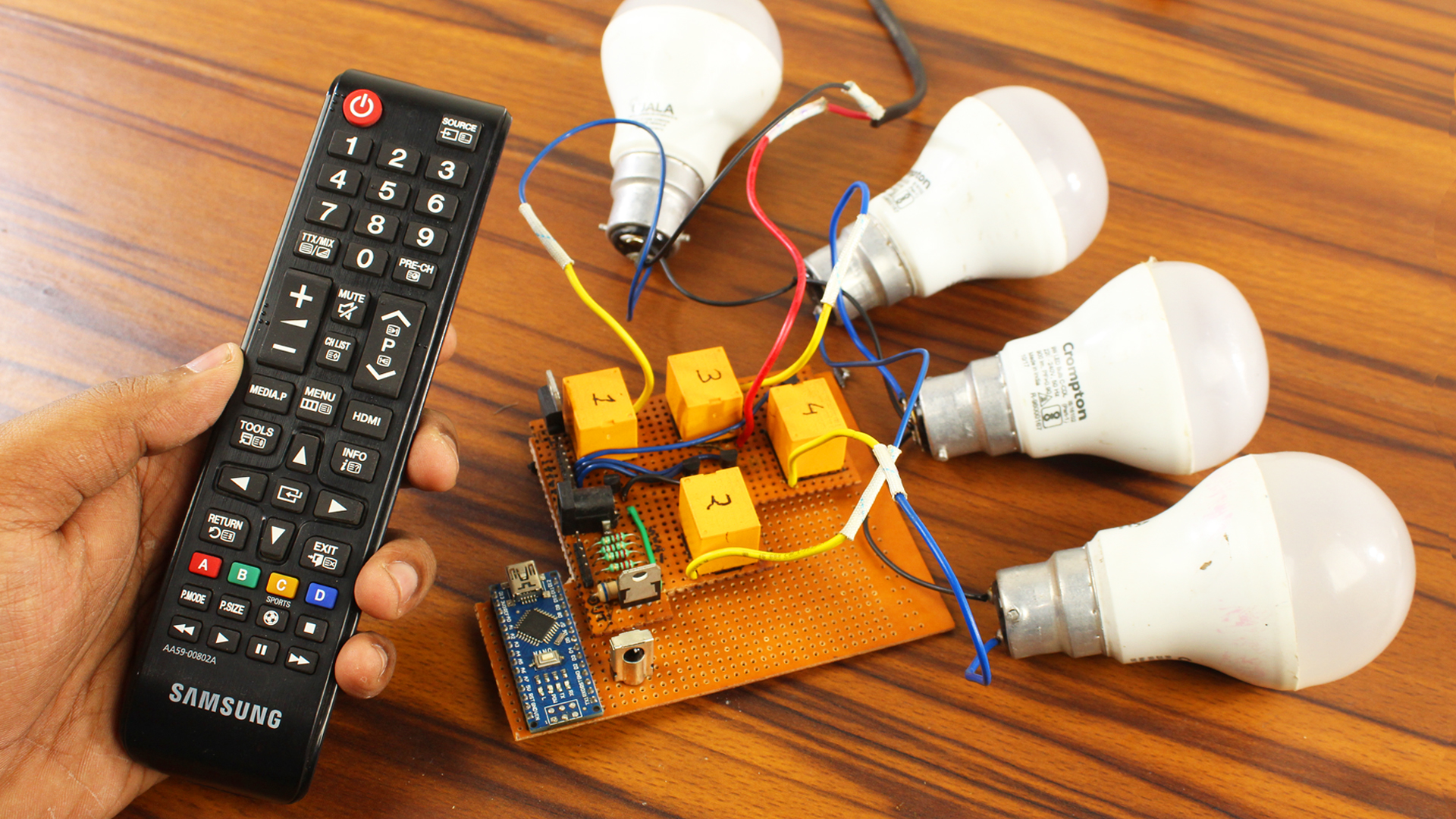
As you might know control, electronic appliances via remote control are a pretty good idea. Using a simple TV remote I can easily turn on or off My room light, fan, bulb or whatever I want, Here I want to control 4 different appliances with my television remote. It’s looking quite complicated, but don’t worry, I have already made a video about it as well as I will explain every single step that I have done so, without wasting any more time let’s find out how we can make our own Arduino Remote Control Switch.
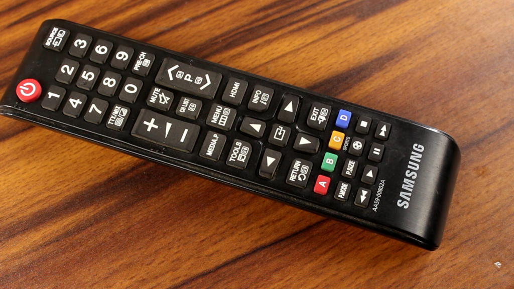
I know you are already familiar with these types of remotes. These are called IR remote. Basically, this type of remotes sent the data through an IR Led AKA infrared Led.

Speaking about Infrared, IR light or infrared lights are everywhere around us who produces heat. Like sun, light bulbs, etc. That means there is a lot of IR noise all around us.
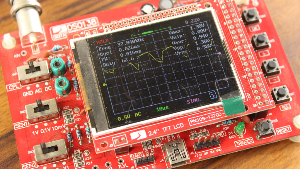
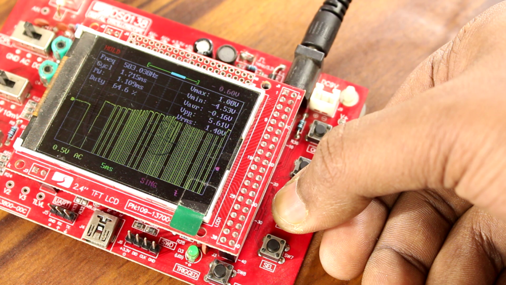
To prevent this noise from interfering with the IR signal, We have to make our signal special. Generally, we use the 38KHz carrier frequency to transmit the data.
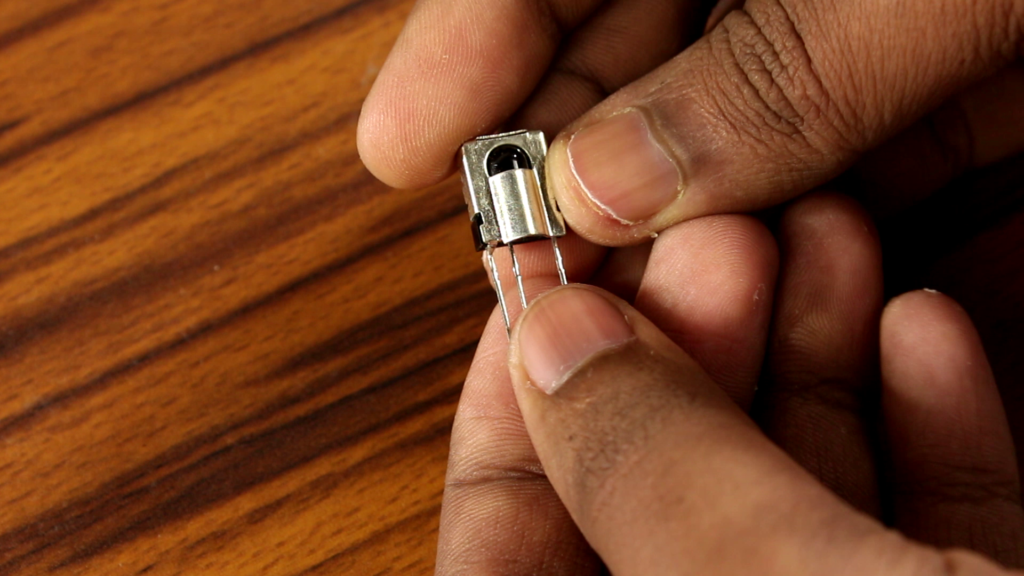
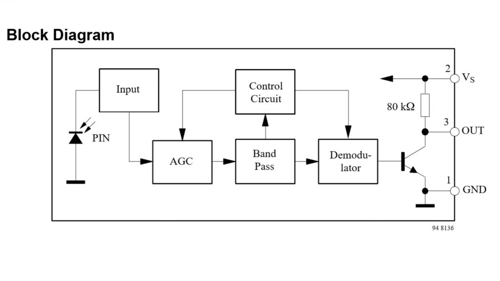
Now it comes to receive the signal from the remote, to do that I am using the TSOP1738 IR receiver which has an integrated amplifier, band-pass filter, and demodulator.
In this way, we can get rid of the carrier frequency and receive only the data signal. Which is good enough for the microcontroller to process.
Another important thing is the data formats. It defines which sequence of burst and pause represents 0 and 1. Want to know more about the data format, then feel free to read this PDF.
To make this project we don’t need to know about data format or whatever. The premade library of the Arduino saves a lot of nerves. So, I am going to use the IR library.
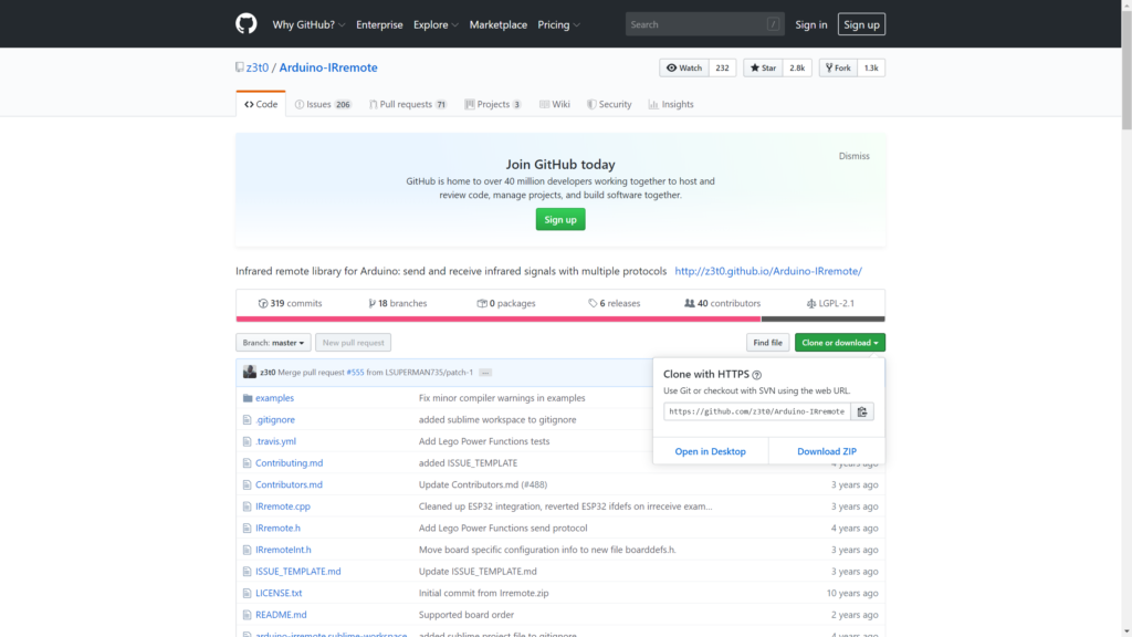
Download: Arduino IR library
To connect the IR receiver with the Arduino I am just cutting the one end of three female jumpers and solder it directly to the receiver. The most important thing do not forget to use the shrinking tube. It prevents unexpected short circuits.
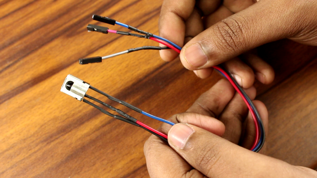
This is the pin configuration of the TSOP 1738.
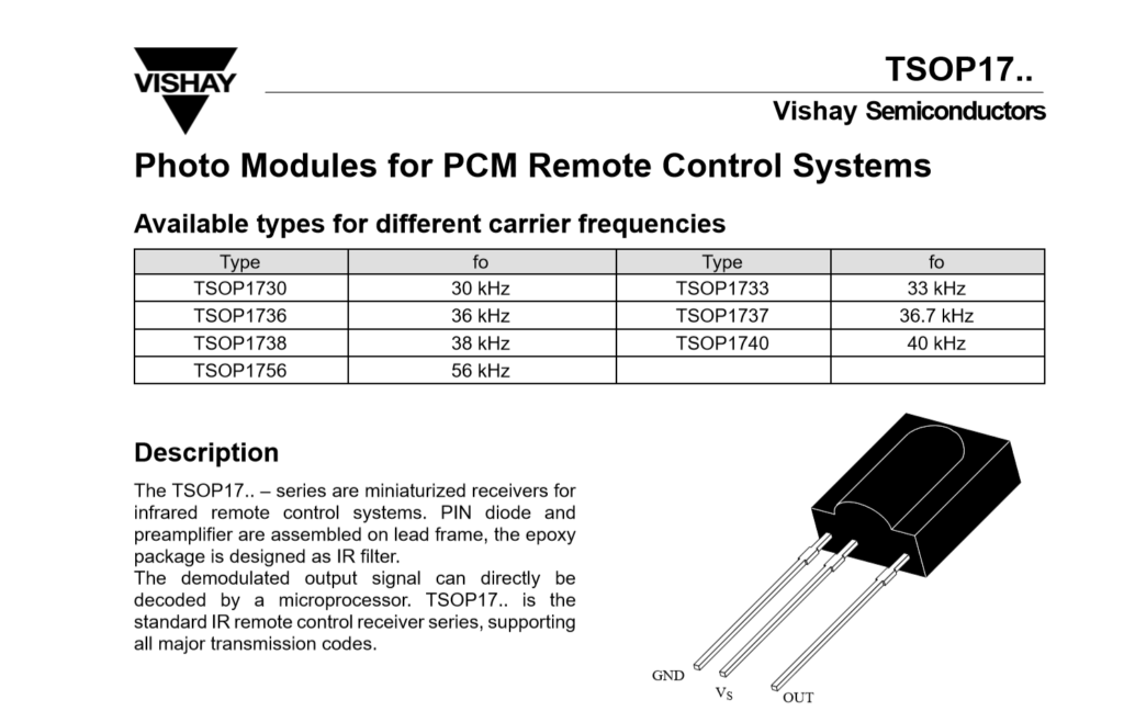
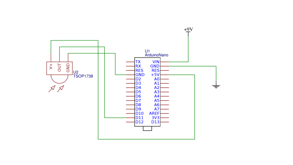
The data pin of the IR receiver can go to any of the digital pins of the Arduino. I choose digital pin 11. Vcc pin of the receiver goes to the 5V pin of the Arduino and GND to the GND.
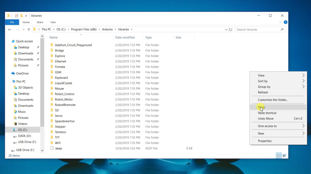
It is the time to use the IR library which was downloaded before. First thing first, Unzip the zip file and copy this file into C:\Program Files (x86)\Arduino\libraries.
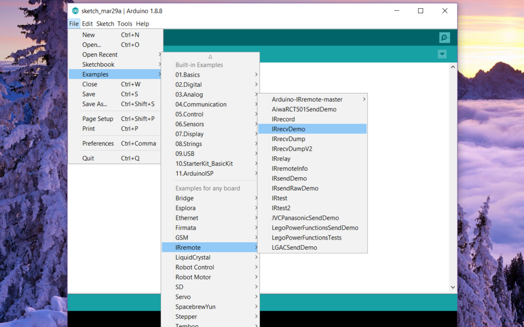
Now open the Arduino Ide move into the example section. then Choose the “IRrecvdemo” from the “IR Remote” section and of course we have to connect our Arduino with our computer beforehand. The next step is uploading. Remember do not change anything in the code this time.
After that, open the serial monitor and press those buttons which you want to assign. As you can see after pressing those buttons from the remote the Arduino generates the hexadecimal code for that particular button. Now note that number, then press the second button from the remote again Arduino generates another code. Let’s note it down. The same thing will be happening for the rest of the buttons.
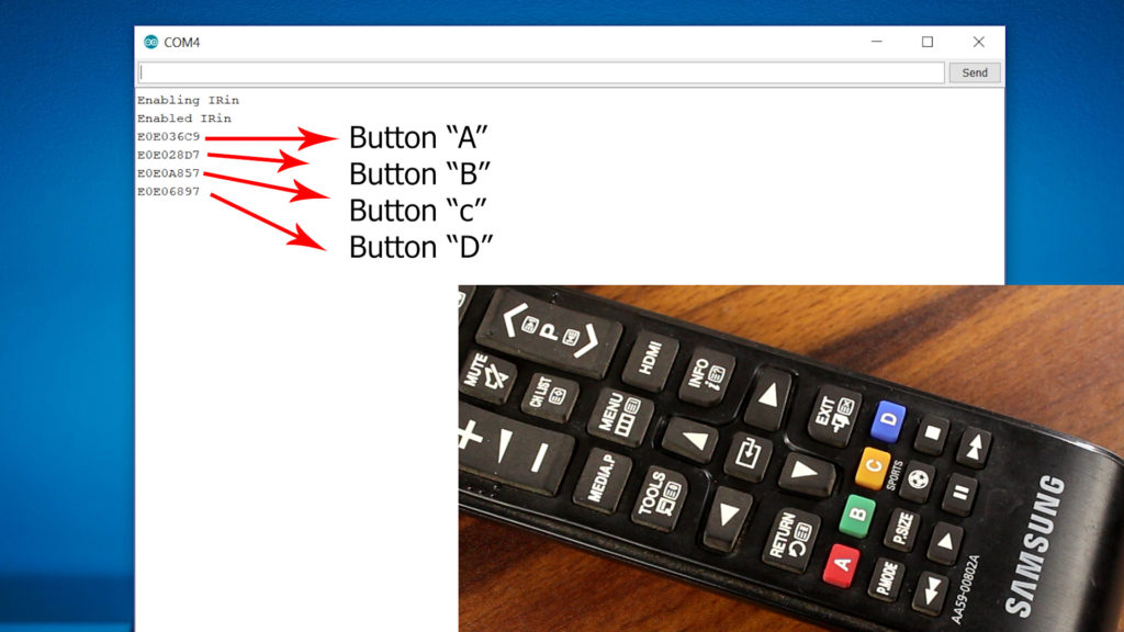
After getting all the hexadecimal codes for the 4 buttons. I am going to edit the code a little bit. You can download the code from the link below.

As I have said this remote can control 4 different appliances simultaneously. So, I have to assign 4 different buttons to turn on/off the gadgets for now.
To drive the appliances we need 4 different 12V relays, but the problem is that Arduino’s digital pin can not provide that much power that these relays need. So, to amplify the power I am using six NPN transistor BC 547.
This is the final schematic for this project. Here the Arduino’s digital pin 11 is connected to the IR receiver and the other pins like pin 13, 12, 10, 9 are connected to the base of the transistor. Those 12v relays are connected to the collector of the transistors and the emitter of the transistors goes to the ground.
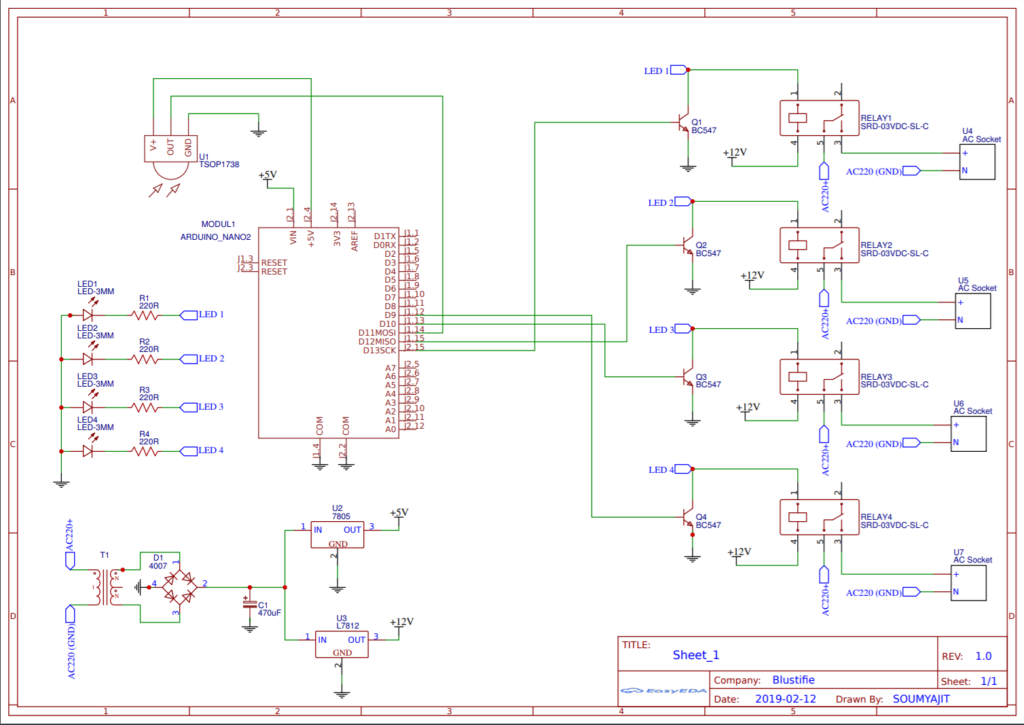
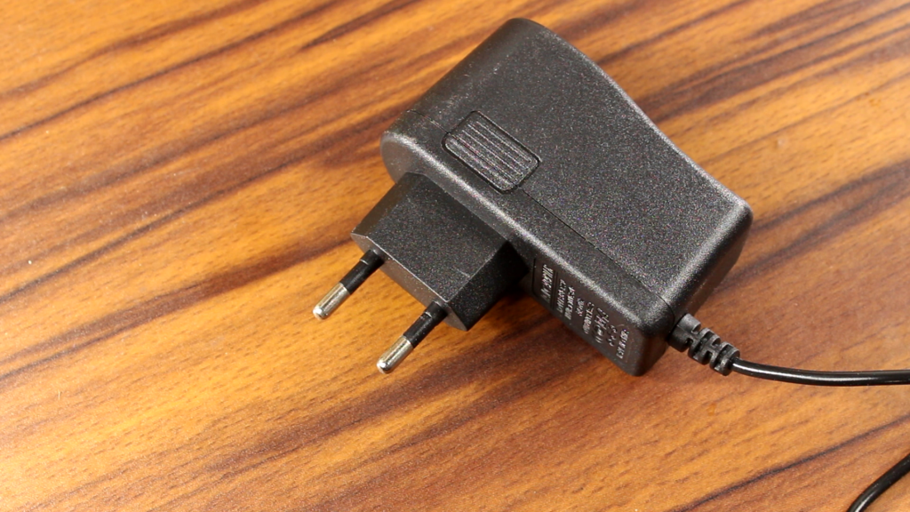
To power the whole circuitry, I am using a 2 amp switch mode wall adapter. Needless to say that I highly doubted the power ratings on this adapter, but it can work properly.
Next thing which I want to discuss is the voltage regulators. I have used the 7809 and 7812 voltage regulator IC. The 7812 IC regulates the voltage for all the components which I have used in this circuit whereas 7809 is used to power the Arduino.
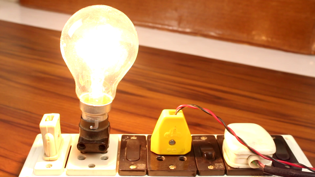
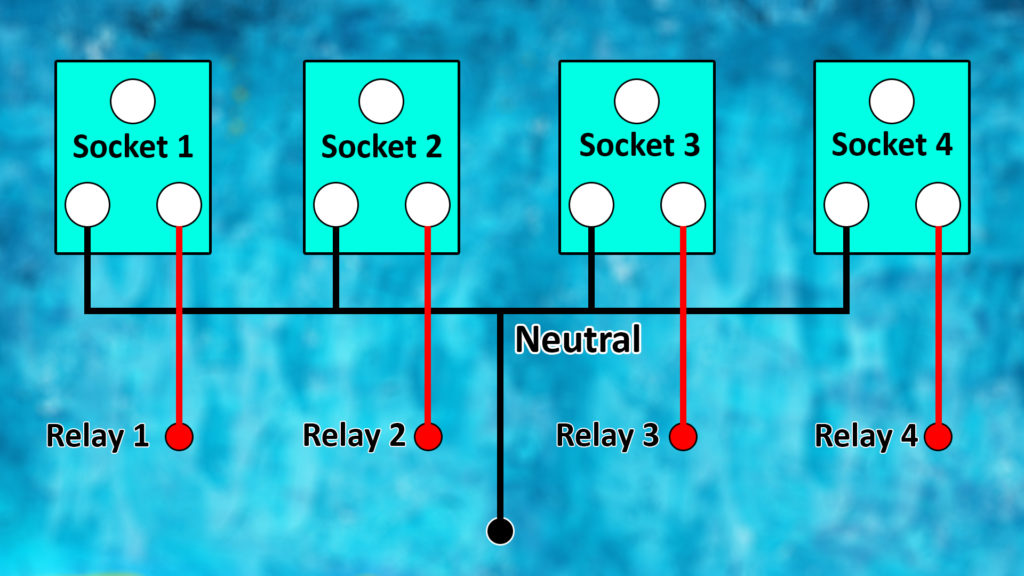
Now, I want to explain about the AC wiring. Please do not build this project with 220V AC if you are just a beginner in the electronics field. One single mistake can damage your hole circuitry as well as those high voltage AC can easily kill you anyway, this is the diagram for the AC wiring.
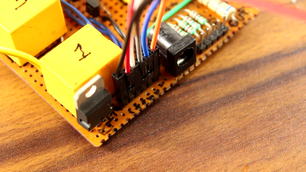
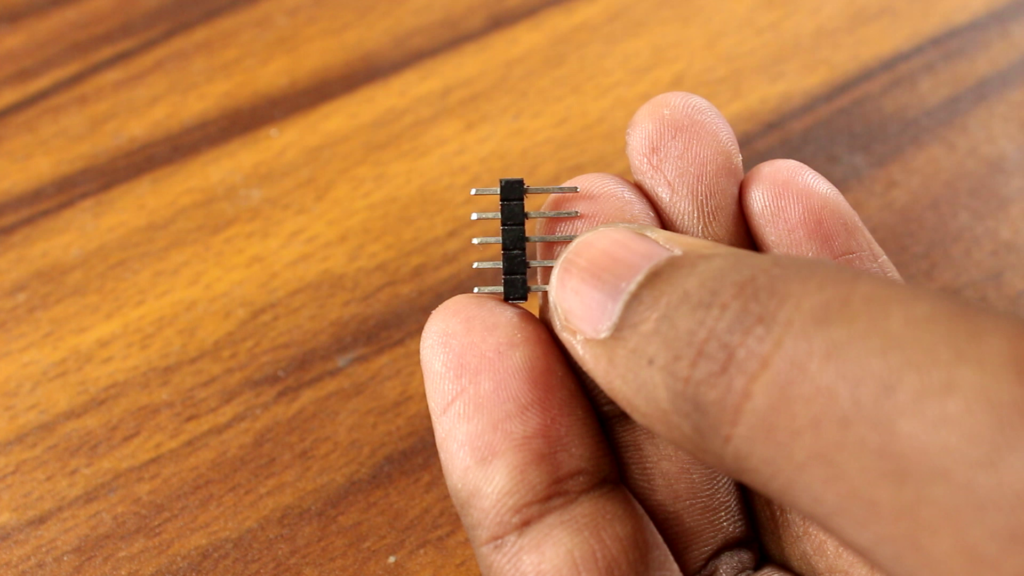
It is time to connect the Arduino with the relay board. To do that I am using some male headers who are sitting on the board and also I am using some female to female jumpers to connect the Arduino with the board.
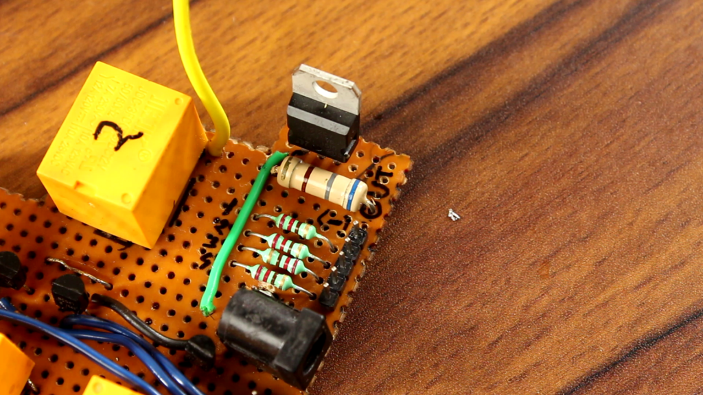
Now we have to prepare some LEDs as an indication. I have just connected four 220Ohms resisters to the collector of those transistor and the positive terminals of those LEDs goes to the 12V positive rail.
I have also used some male headers to connect those LEDs with the relay board.
Parts List
There are lots of components are needed to build this project, I have listed all them below:
- Arduino Nano (1)
- TSOP 1738 IR receiver (1)
- 12V Relay (4)
- BC 547 Transistor (4)
- Male Header (15)
- Female to female jumpers (11)
- DC Jack (1)
- 12V 1AMP Adapter (1)
- 7809 & 7812 Regulator IC (1)
- 220 Ohm Resistor (4)
- 680 Ohm 1 W Resistor (1)
- 0.5mm Copper Wire
- Dot printed Perfboard (1)
- 5 Pin Sockets (4) (Optional)

I hope you guys understand everything regarding Arduino remote control switch and its functions. If you have any queries, questions then don’t hesitate to ask me in the comment section below. Thanks for visiting.