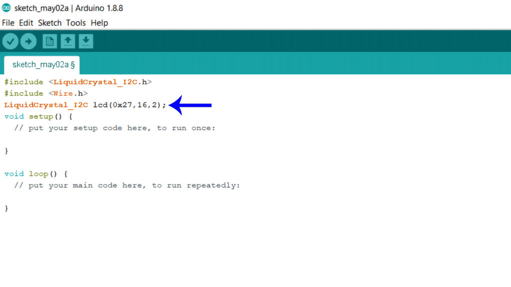
In the Arduino projects, displays are pretty common when it comes to showing some values and information. There are plenty of display modules out there that can be used by electronics hobbyists. Today, we are only talking about LCD displays. As I told you previously in the article about “How to connect an LCD with Arduino?”, there is a lot of variations available on the LCD family. They are divided by their total character counts. Some have 16, some have 32 and finally, some have 80 characters too in total. Obviously, we can choose between them according to our needs. Increasing character numbers obviously increases its cost. Right now, if you are thinking that interfacing with an LCD is a pretty hard task then you are completely wrong. Just you have to use a couple of lines of codes (Shown on the image below) on the Arduino ide and you are done.
Frankly speaking, with the help of this code, you have to do a lot of wirings between LCD and Arduino. You need to provide connections at least 6 pins of all the 16 pins of the LCD. It’s a complete hassle and also problems which can be a problem when GPIOs are very limited. Here, I2C LCD modules come to save us. By using only 2 GPIOs of the Arduino, it can communicate with the display with ease. Let’s dive deep into the module to learn the basics, understand its functionality, and finally what kind of things you should keep in mind before using it. After all of these, I can assure you know everything that you need to know to use a ‘Character I2C LCD’ with Arduino. I have also added lots of example codes that you use to polish your coding skills.
Watch the Video First:
LCD Basics:
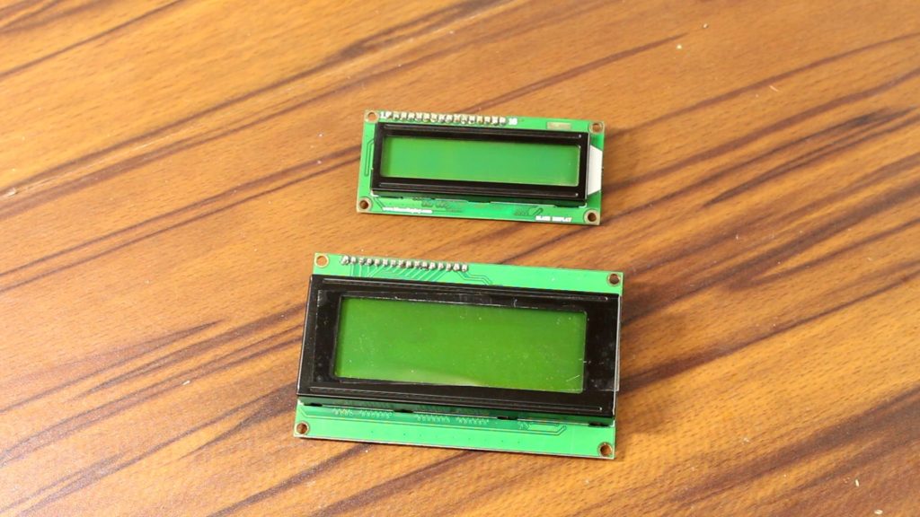
These LCDs are ideal for displaying text and numbers, hence it got the name ‘Character LCD’. If you look closely at the LCD, you can see the small rectangles that form the individual character of the LCD. Each rectangle is made up of a grid of 5×8 pixels; either it is a 20×4 LCD or 16×2 one. It is funny to say that we can easily use a 20×4 LCD in the place of 16×2 One or vice versa. It doesn’t require any special libraries or codes except you have to only tell the Arduino about the character number that you’re using. It is possible due to the HD44780 controller. Both the modules are based on this. So, switching back and forth doesn’t create any problems.
I2C LCD Basics:
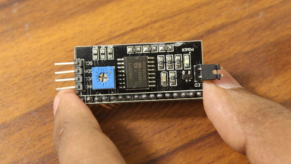
Physically, most of the ‘Character LCD modules’ have the same 16 pins to communicate. A standard LCD typically requires around 12 connections which can be a problem when GPIOs are very limited. Here, I2C LCD modules come to save us. By using only 2 GPIOs of the Arduino, it can communicate with the display with ease. This module features a 16 Pin IC for I2C communication (PCF8574 to be specific) and a potentiometer to adjust the LED backlight. In terms of communication, it has 16 pins to connect with an LCD and for the I2C communication that features only 4 pins which are VCC, GND, SDA, and SCLK.
How to connect the I2C LCD to Arduino
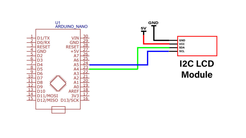
Connections are pretty simple. Without worrying about anything, just connect all of the 16 LCD Pins to the module sequentially. I don’t want to solder them together right now. So, for the solid connection, I have used just a simple breadboard. It is time to connect the module with the Arduino. From the top, the first two pins are VCC and Ground. Next are the data pins that are serial data & serial clock which actually consume Arduino’s GPIOs. SDA (Serial Data) and the SCLK (Serial Clock) will be connected with Arduino’s analog pin A4 and A5 respectively.
What Should You Know About I2C?
Here Arduino acts like ‘Master device’ and the module itself is a ‘Slave device’. In case you don’t know, we can connect up to 128 slave devices with Arduino by using just two pins A4 & A5 but here, we have to remember all of the slave devices should have different I2C addresses otherwise the data can collide and the hole communication can fall apart. If you’re thinking that this is the only module that uses I2C then you’re completely wrong. There are lots of other devices which use this communication protocol. You can also use them simultaneously with this I2C LCD module but their addresses should be different.
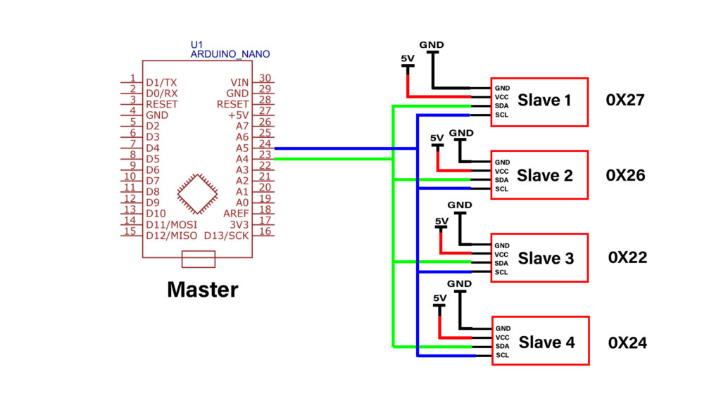
When the address is the key line of the communication then the question arises how will we know that? Sometimes, the address is written on the module itself or on its data sheet but sometimes, we have to find the address by ourselves.
How to find the I2C address of my LCD?
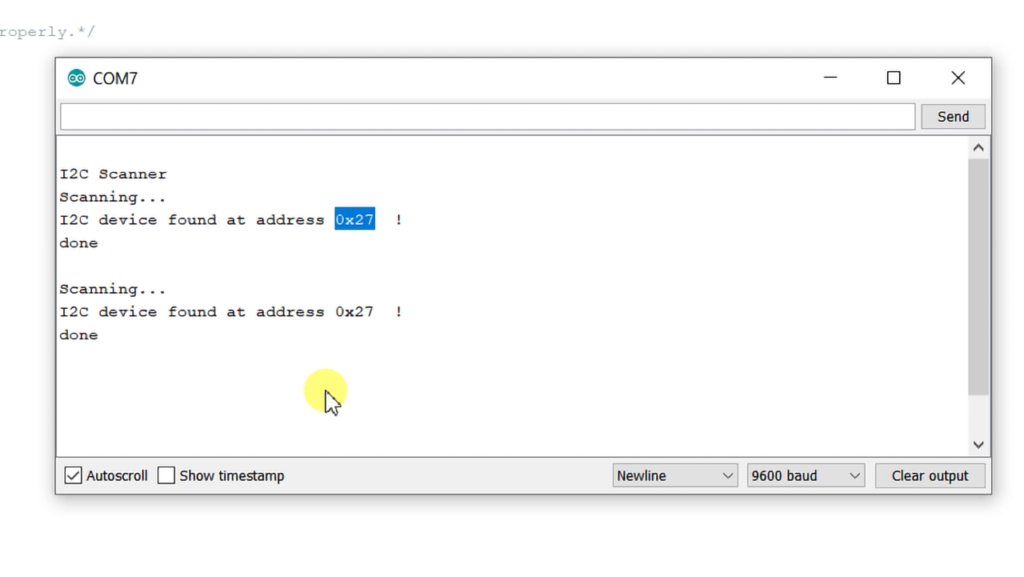
Thankfully though, by using this simple piece of code, we can scan the I2C-bus for devices. If a device is found then the Arduino displays the address of that device or devices; if there is multiple I2C devices connected in the serial monitor.
This LCD Module, for example, uses ‘0x27’ which Most I2C LCDs normally do. This is eventually the default address of most of the I2C LCD modules but it may be different on the case of yours then better to verify it by using this piece of code.
Let’s Write an Example Code…
Now you know, How the hardware should be, for using an LCD. It’s time for programming. I am not explaining “What is I2C? How does it work?” etc. to make the stuff simple. Here we use a library called ‘Liquid crystal I2C’ which includes many built-in functions that make programming the LCD quite easy.
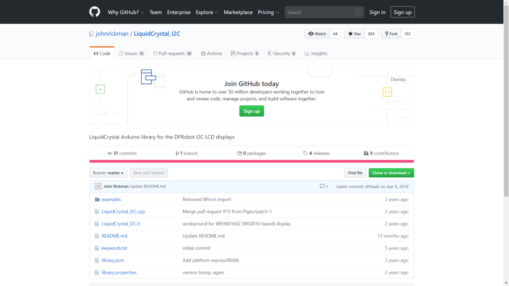
The latest version of this library can be downloaded here on GitHub or click the button below.
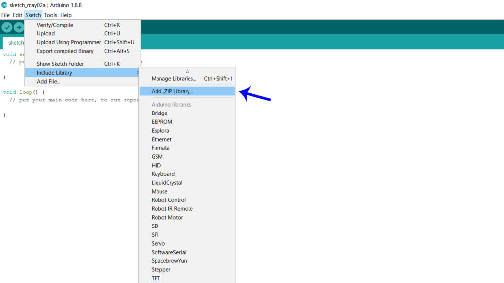
You can install the library by going to Sketch > Include Library > Add .ZIP Library… in the Arduino IDE.
The library does include some examples that you can use but you will have to modify them to match your hardware setup.
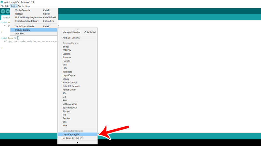
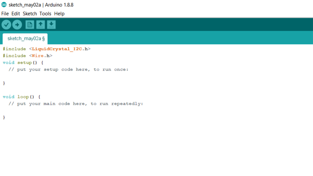
For the I2C communication, ‘Wire.h’ library comes pretty handy. It should come pre-installed with the Arduino IDE.
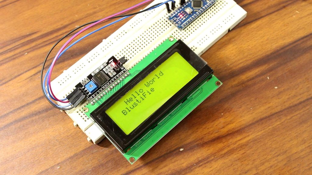
Here in this example, I am using a 20×4 LCD. Here, we are going to display the classic ‘Hello World!’ on the first line of the LCD and ‘BlustiFie’ on the second line. Something like the Image below:
Anyway, let’s understand the code line by line. First, we include the required library as I said. we need both the ‘wire.h’ and the ‘LiquidCrystal_I2C’ library. The next step is to create an LCD object with the LiquidCrystal_I2C class and specify the address and dimensions. For this, we use the function LiquidCrystal_I2C (address, columns, rows).
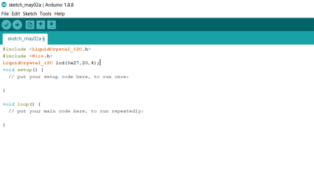
Speaking about the address, we have to put that address on what we got previously from the serial monitor. Obviously ‘0x27’ is the I2C address of this particular module. 20,4 is the LCD character configuration. I am using a 20×4 LCD. If you use 16×2 then change this into 16,2.
Next on the setup section, let’s initiate LCD and its backlight and finally, from the loop section by determining the cursor position which is, in this case; 0,0. Let’s print something on the LCD by using some basic LCD commands.
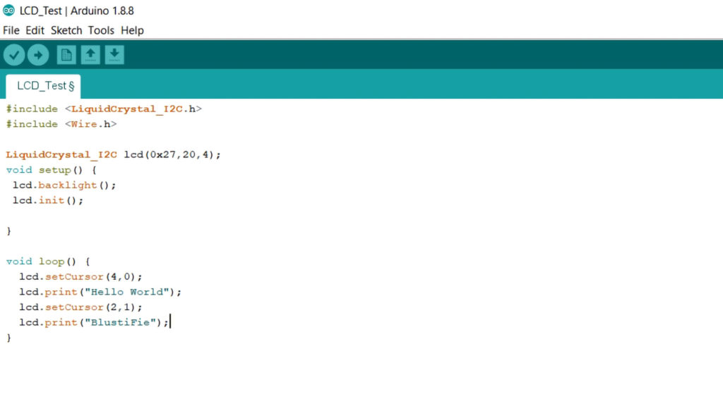
Now upload the code. As you can see, the LCD shows the programmed message without any problem.

If you’re confused yet then feel free to check my video about “How to Use an LCD With Arduino?” I have explained everything there.
Note that, you need to place quotation marks (” “) around the text since we are printing a text string as you have seen on the image. When you want to print numbers, no quotation marks are necessary. Just like this…
(Image Printing number on a LCD) (Codes and Practical)
Do Not Forget to Adjust the Contrast Of the LCD.
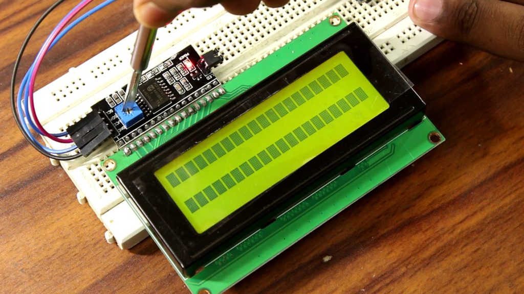
After powering the constellation, sometimes, you notice that after you have wired up the LCD, you will need to adjust the contrast of the display. On the I2C module, you will find a potentiometer that you can turn with a small screwdriver.
Read More: Arduino Remote Control Switch: On/Off Room Light With TV Remote
Plugin the USB connector of the Arduino to power the LCD. You should see the backlight light up. Now rotate the potentiometer until one (16×2 LCD) or 2 rows (20×4 LCD) of rectangles appear.

Let’s use this LCD with something realistic…
Let’s make a simple voltmeter that can measure voltage up to 5V. After adding couple of lines into the codes, the Arduino achieves the capability to read the analogue value and convert it into a voltage.
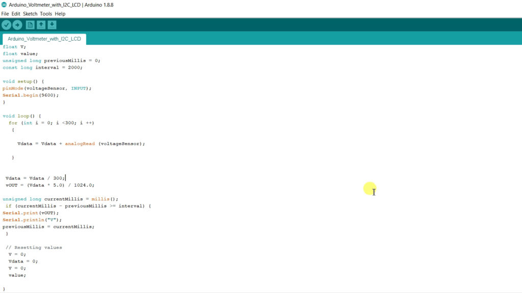
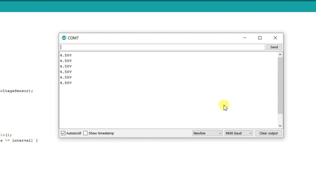
Let’s print whatever we calculated in the serial monitor.
Now let’s print the values on the LCD. First, we have to include all the libraries, choose the I2C address and LCD type. Then we have to initiate LCD and its backlight. Now by doing a bit of modifications, we can print the calculated voltage value on the LCD along with the serial monitor. For that, I have added these two lines as shown in the image below.
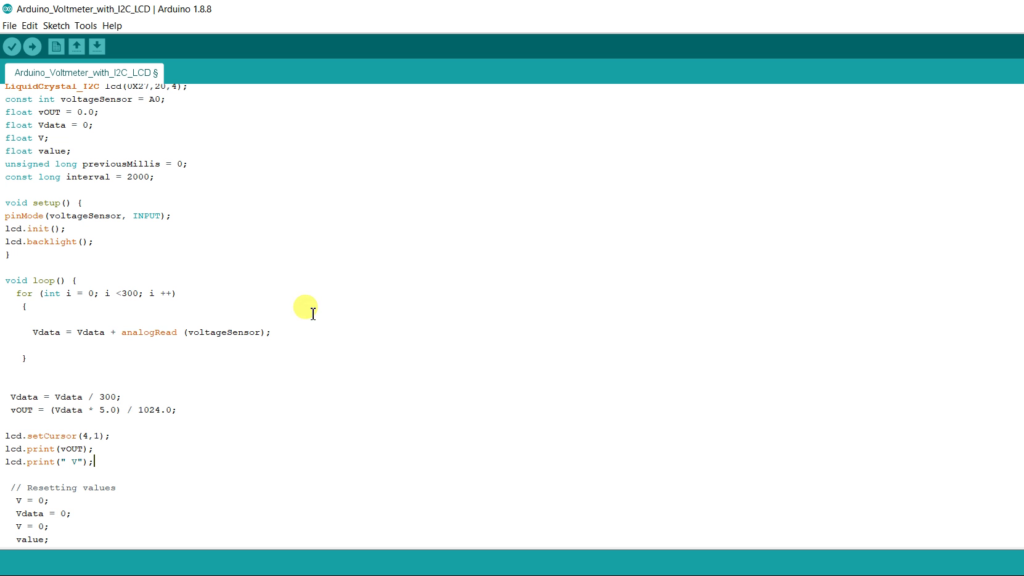
First line actually prints the voltage and the second line provides the unit (Volt) next to the voltage value. Now upload it.
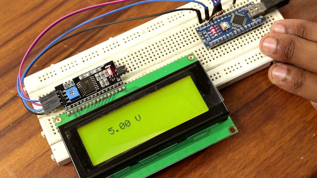
As you have seen in the previous image, the code just works fine but in real life, when we deal with two-decibel values or two characters simultaneously then this code creates a problem something like this.
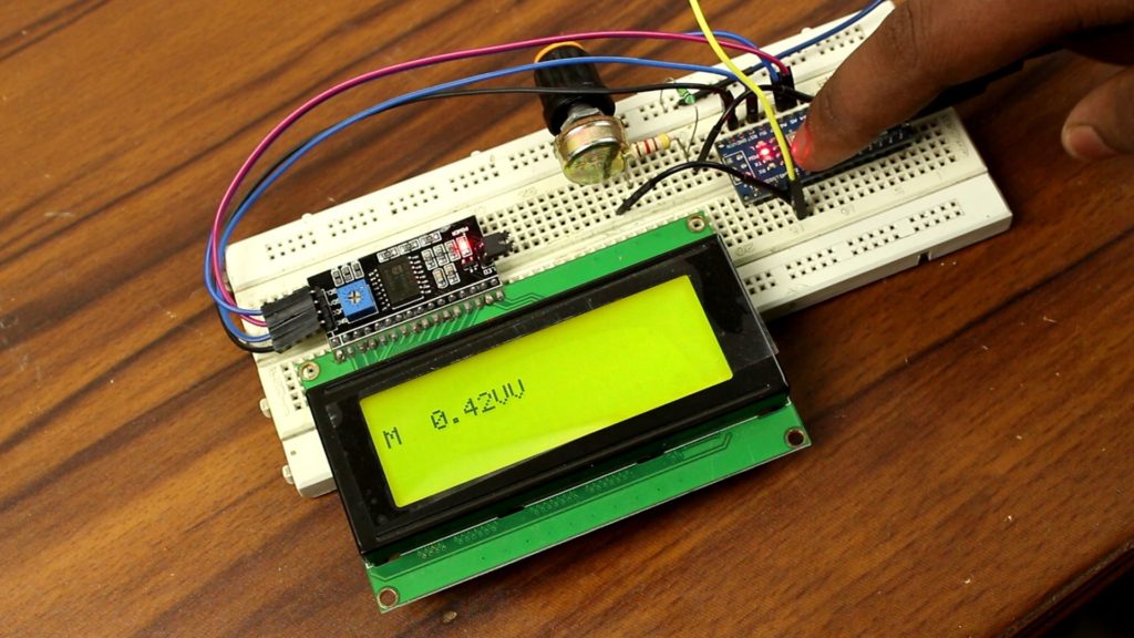
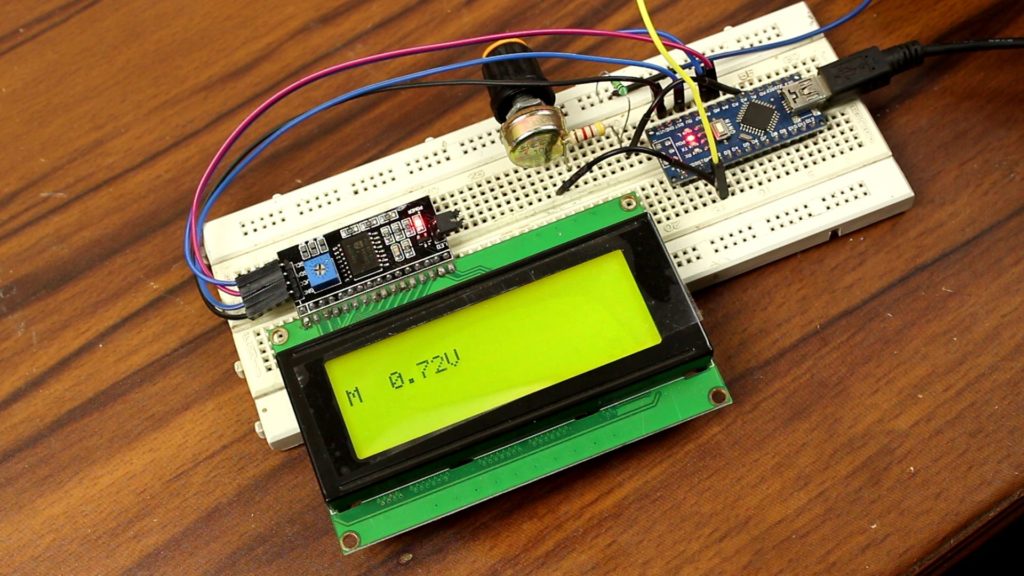
which is quite a bit annoying and seems buggy. Actually, here the LCD never reset to clear the one ‘V’ character. According to the codes unit volt aka ‘V’ prints next to the values. When we measure 13V it prints next to the values. When we measure such voltages below 10 volts ‘’V also prints next to the values but the old printed ‘V’ is not removed from the LCD. This problem will stay until I restart the Arduino. To solve this issue, I have written an LCD clear command in this configuration. The Millis function actually put some delay into the system.
An Important Function, ‘LCD Clear ()’
As an example, we still deal with the previous voltmeter code. To solve the overlapping problem, we generally use ‘LCD clear’ command. To use this function, you have to add a delay between what you’re printing on the display and LCD clear. To put a delay, we just simply use ‘delay ()’ function something like this…
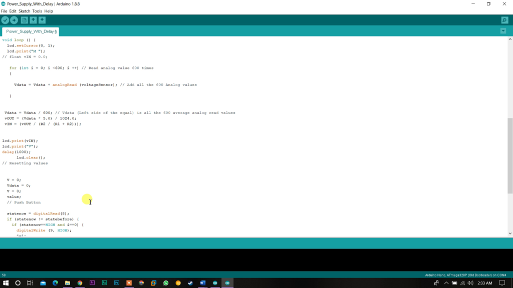
Or we can use ‘Millis’ function in this configuration.
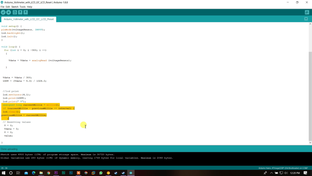
It also put some delay into the system. Arduino prints a value into the LCD and it also continues the loop and detects any changes into the analog pin. If anything changes, Arduino detects it again, converts the value into the voltage, and prints the value on LCD by replacing the older one. It repeats this process until the set time in the ‘Millis function’ has been reached. At that certain time, Arduino clears the LCD and again prints value into it. This way no overwriting occurs.

You can say, why Millis function? a simple delay function can do the job. (Click the button below to get both test codes)
Hmm, yes, you’re probably right but think something like this; I want to add a pushbutton with the system to turn on slash off an LED. If we use delay function anywhere on the code, the Arduino sticks for that certain time and can’t execute any commands. If I pushed the switch now, the input most of the time ignored by the microcontroller.
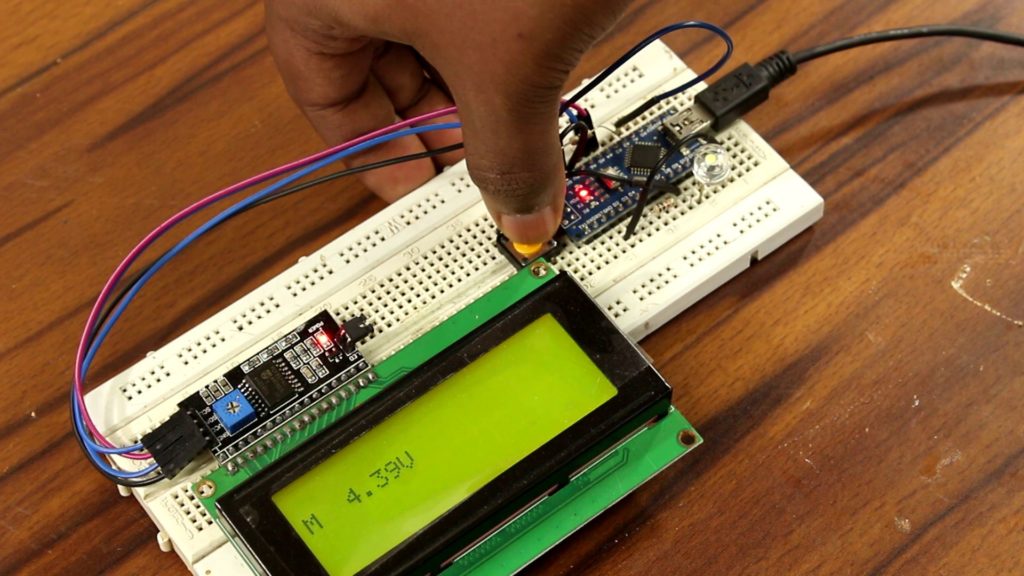
In a nutshell, communicating an LCD with the help of I2C bus is not a rocket science. By using couple of extra line of code, you can easily use the module. Apart from that, rest of the system as same as we normally do.


