
A bench Power supply is a very important piece of equipment that every electronics hobbyist can own. It helps to limit the voltage and current. That is mandatory when we’re testing circuits, charging batteries, and testing components, as well as gadgets but the problem, is these power supplies aren’t so cheap and a beginner doesn’t want to invest such a lot of money in a piece of equipment.
In this article, we will design a bench power supply that is very cost-effective and fully modular so everyone can DIY it with some basic knowledge about electronics.
First of All, Watch the Video…
N.B. Do not replicate this project if you’ve no experience with electronics. This high voltage is lethal!

Parts List to Design a Bench Power Supply
First of all, we need a module that can control all the voltages and current limiting stuff. I used LTC3780 step up – step down converter which is a really powerful buck and boost converter that can handle up to 130W and with a proper heat distribution system, it can go beyond that (I’ve tested up to 245W of power output capability for a couple of minutes although I will not recommend you to take such a huge amount of power unless you design a proper heat distribution system). I have used two of these modules to create a dual-channel lab bench power supply.
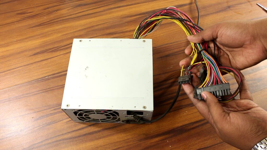
Next, we need a power source that can provide anywhere between 5 to 30V. So, I have used my old PC power supply which you may know has 3.3V, 5V, 12V, and -12V rails. I have used only the 12V rails. Also the -12V one which I have discussed later in this article.

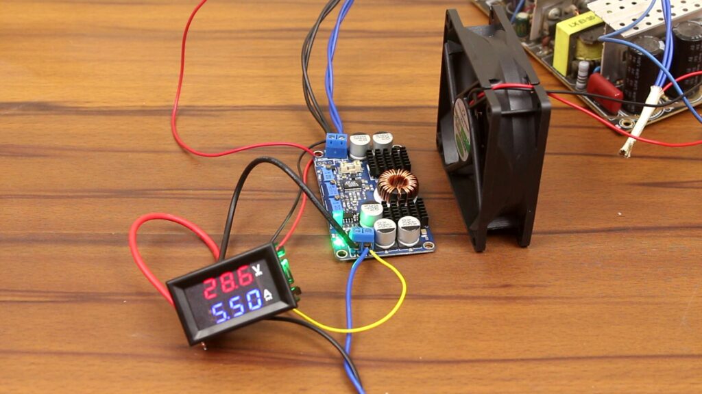
The 3rd most important piece of modules, we need is these voltage and current meters. These can measure up to 30V 10A. They are pretty accurate if you use them like the configuration I have mentioned later.

And of course, you need some multiturn potentiometers which you can buy or can DIY as I have shown in the video below.
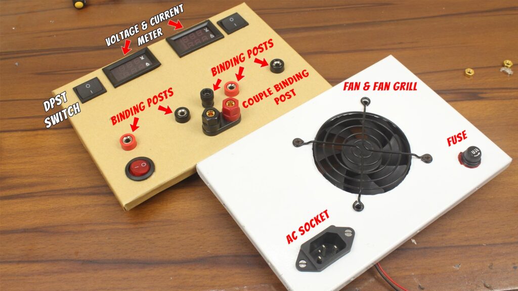
Also we need some complementary components like fuse holder, AC socket, Fan, fan grill, screws and 4 binding posts. (Optional) A ‘couple binding post’ and single ‘binding post’ – if you want to take out -12V rails.
How to Use PC Power Supply as a Bench Power Supply?
Of course, we can use ‘PC Power Supply’ as a beginner’s bench power supply but we’re not here to do this rather we’re here to modify the PC power supply for the LTC3780 modules.

The power supply I’m using that according to its label, can output 24A on its 12V rail, Total 288W. Good enough to proceed but with its output wires it is definitely not recommended. These thin wires single-handedly, neither support 288W nor 130W of load, and there are also a bunch of extra wires are coming out from the PSU that eventually have no use. Most importantly, we need to get rid of this enclosure because we can’t fit LTC3780 modules inside it.
Modifying the PSU…
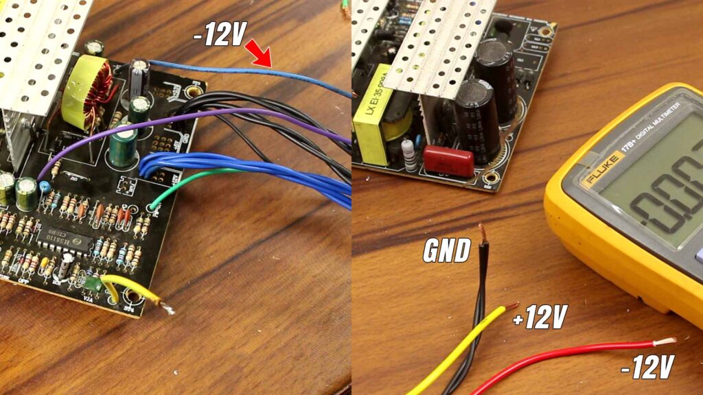
So, I have removed the enclosure and have taken out all the unnecessary wires. Also, I have replaced four 12V carrying yellow wires and 4 ground wires with 0.5sq mm blue and black wires respectively as shown in the image below.

Now, I should mention that I have short the green wire with GND to keep the PSU (PC power supply) ON forever. Basically, by shorting green and black wires together the PSU turns On and disconnecting them, the PSU turns off. (Image)

Also, I haven’t removed the blue wire. Through this, the PSU can provide -12 volt against GND. I have replaced this wire with a 1mm thick Red wire to get -12V rail from my power supply.
The configuration looks like this +12V GND & -12V. The +12V is not the output of the buck-boost converter modules this +12 is the direct output of the SMPS. So, I have soldered a 1mm yellow wire (for +12V) and two 0.5mm thick black wire together (for GND) with the SMPS.
Next, I have taken out the fan from the PCB and have soldered two wires to later connect the fan with it.

That’s it. Output terminals are ready, it’s time for the input. In my case, the White wire is ‘Phase’ and the black one is ‘Neutral’ and this green wire is ‘Ground’. I have replaced them with blue, black, and green wires which are phase, neutral, and GND respectively.

How to Measure the Outputs in the Bench Power Supply?
I have mentioned the voltage and current meters in the ‘parts list’ section in this article. Now it’s time to use them. I have provided the wiring diagram down below.

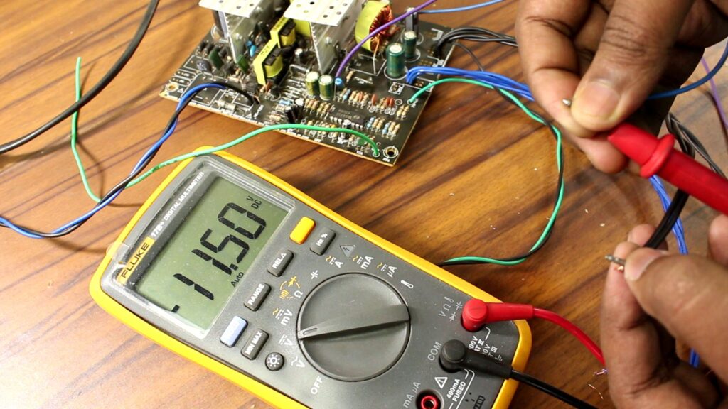
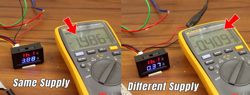
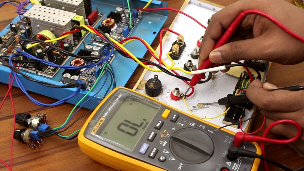
Remember, never try to connect the positive and negative supply wires of the meter with the PSU’s output. Your measured values may be getting distorted aka imprecise for this. You have to use a separate power supply for precise measurement.

As you can compare the ‘current’ reading on the meter and on the multimeter, it is distorted with the use of the PSU’s output but with the different power source, the current value is pretty accurate.
How to Use LTC3780 modules?
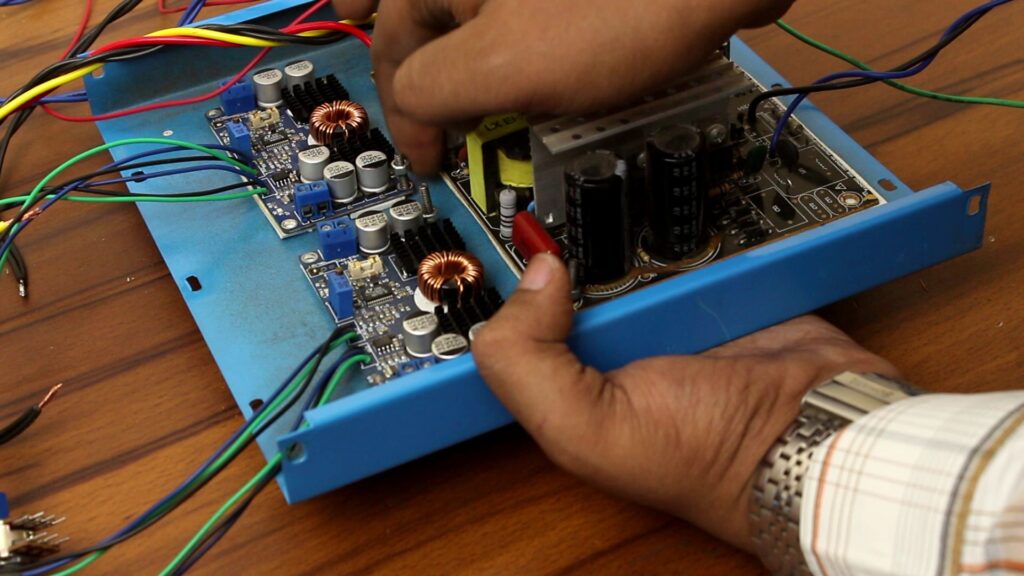
First of all, connect the 12V output of the PC power supply to the LTC3780 module’s input and use at least 5V on the pin (shown in the image below) to activate the output of the board. This later comes very handy to turn on/off the output of the module.

Now we can tinker with these three potentiometers. the far left one controls the output voltage – the maximum it can reach up to 29V and minimum 0.7V.

The trimmer in the middle can limit the current. Minimum is 0.11A aka 110 mA and maximum 7.61 A at 1V.

The third trimmer should be untouched because it is for under-voltage protection which we do not care about in this case.

Modification with LTC3780 modules
Here is nothing much to modify, I have just replaced the 500K and 200K trimmers of the module with multiturn potentiometers which I have made by myself with the help of those trimmers that I have removed earlier.

N.B. For the second supply channel, I have used the second LTC3780 in the same configuration. This time, the only difference is; I have only used the other set of blue and black wire of the power supply on the input of the module.
Enclosing the Bench Power Supply
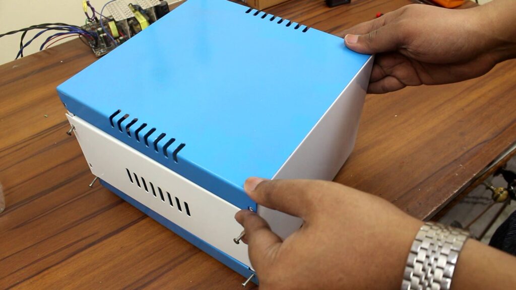
To pack all the components together, I’ve used the metal box as shown in the picture below.
Preparing the Metal Box
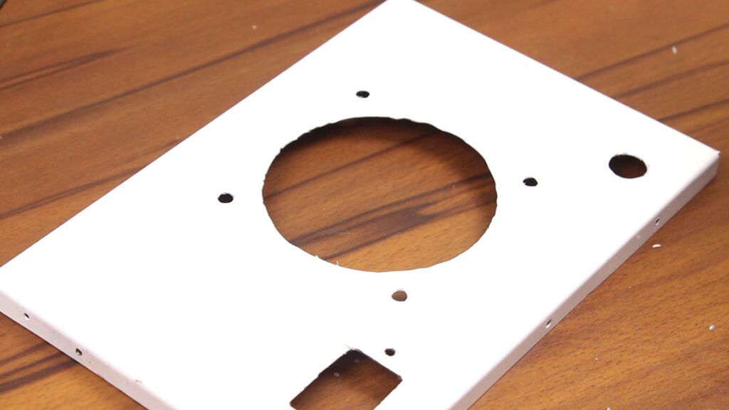
First, I have covered the front panel with the masking tape and have done some basic measurements where I want my external parts to be placed; I have marked those spots, and by using a rotary tool and drill machine, I have made places for the displays, binding posts, and switches.

There are also some components on the back like a fan, AC socket, and fuse holder so again, my drill machine, rotary tool come very handy. This time the only difference is, I have used sanding attachment with my rotary tool. Additionally, I have used a chisel to expose the fan from the backplate (You can find the details in the Video).
Assembling Time…
Next, I’ve assembled all the components on the front and back panel except the potentiometers because they are already soldered with the LTC3780 modules so we have to put them in the front plate later.

N.B. I have changed the theme of the box a little bit according to my taste so don’t worry if you don’t like this sticker.
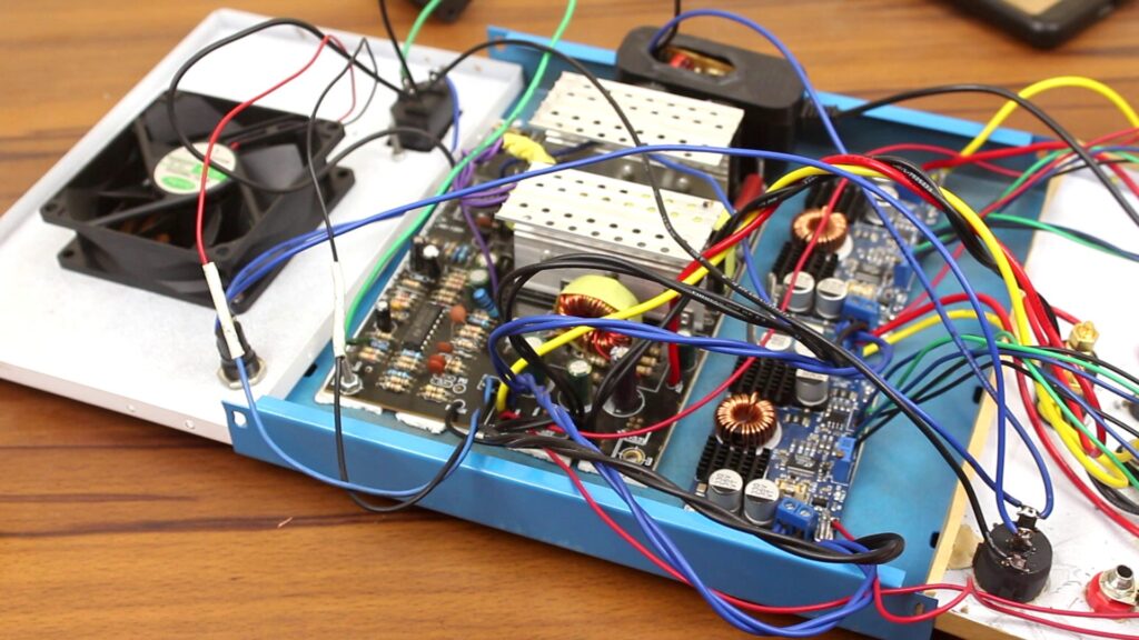
Now, all we have to do is to set up all the circuit boards inside the enclosure. I have placed them in a suitable location, mark their screw holes, drill on those holes, and with the use of double-sided tape as an insulator, I’ve tightened all the circuit boards with the enclosure with some nuts and bolts.
Ok, now let’s start the connection. I’ve started from the back panel. I have soldered the fuse AC socket the switch of the front panel and the PSU’s circuit board together as shown in the picture below.

The front ON/OFF switch has an indicator light that runs on AC 220V so the switch needs a neutral line for that. Which I have set up from the AC socket’s neutral line.

On the front panel, I’ve started off from the binding posts. First I’ve set the +12V and -12V with the couple binding post (Red is +12V and Black is -12V) and the single binding post has been set to the GND.

I have connected all the outputs from the LTC2780 modules to them. I have two sets of Red and yellow wire. Red should be connected with the Red binding post because it is positive and yellow will be connected with the black binding post through the meter’s current measuring path (Thick black wire connects with the yellow wire and thick red wire connects with the black binding post). Everything is described in the image below. The yellow voltage sensing wire of the meter should be connected with the red binding post.

Ok, when everything is set, I have also set the potentiometers with the metal body using nuts.

Of course, verification of body short is very essential so, I took my multimeter and make sure that there is no contact between the body and binding posts.
Afterward, I have prepared DPST switches. One section controls the power-on signal of the LTC 3780 module and the other section turns on the meters on the front. Don’t forget to use a separate power supply for the meters (I have used a 6V power adapter). I first take it apart, cut down its power prone, and have soldered the AC power wire with it which phase is connected with the output of the switch, and the neutral is connected with the AC socket.
Lastly, I’ve connected the fan wire with the PC power supply.
N.B. Don’t forget to use insulators on all the wire joints otherwise the system may short badly and the whole system can be burned down in a fraction of a second!
Let’s put all the pieces of the box together. It is quite a simple job to do but you have to be cautious about the wires. They should not be punched by the box.

Also, you have to use knobs on the potentiometers to keep them handy to use although there, I have to cut down the axle of the potentiometers to perfectly set the knobs.

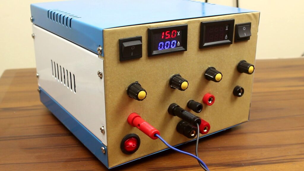
After putting the top lid back in place, I have tightened all the screws and we are done.

Testing the Bench Power Supply
Well, I need a 2A fuse on the bench power supply’s first run. After connecting the AC power into the socket, I have pressed the power switch and thankfully, there is no explosion.
Next, I have turned on the other two switches to actually activate the variable voltage and current outputs. Only pressing the main power switch, just turns on the output of the +12V and -12V section.
How to use the Bench Power Supply?
Actually, it’s pretty simple, first, you need to set the voltage you want by using the voltage adjustments knob then short the two output terminals and set the output current using the current adjustment knob. That’s it.

In terms of this design, everything is as same as that. Let me tell you the locations of the knobs. The far-left one controls the voltage and the second one controls the current of channel 1. 3rd potentiometer controls the voltage and the 4th potentiometer controls the current of the supply channel 2.

Testing the Bench Power Supply
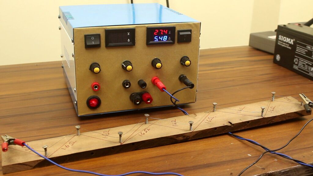
To connect the output with the binding posts, we should use banana plugs. I have soldered the wires inside it and also have soldered crocodile clips on the other end of the wire. We are finally at the end of this project. So to test its output, let’s put some loads on it. Now, I have used this contraption which has a long nichrome wire.

I’ve connected the two terminals of the power supply with this contraption and you can see the meter reads the voltage and also the current consumption of this resistive load.
In Concluding Lines…
So, I can say this DIY Dual Channel power supply is working perfectly fine. This is a very cheap way to build a power supply for your lab. But please be careful about the AC voltage you’re handling. One simple mistake can forfeit your life. Hope you guys have found this video and the article about DIY Bench power supply helpful as well as enjoyable if so then don’t forget to subscribe our YouTube channel and let us know if you’re facing any issue while trying to recreate this project. Thanks for visiting & appreciating our work.