Having an air cooler for 7 years I am really very annoyed with filling up water from time to time – at least twice with around 6hrs of usage. It’s happening because the pump is constantly circulating the water through the cooling pad or evaporating pads or wet curtains whatever you say. Because of the constant circulation, evaporation unnecessarily increases which causes water wastage. It’s actually quite easy to fix this issue. We need a dedicated timer whose job is to turn on/off the pump every 6 minutes. That reduces water wastage but there’s also another problem. While filling up the cooler or while the water goes below the critical level the only way to understand is the mechanical water indicator as shown in the picture below. If we fill the tank with excess water the tank just overflows which causes a mess inside our home, if the water goes beneath a certain degree pump could suck the dust and dirt from the bottom of the tank of the cooler – I need a water level indicator. So, without further ado let’s fix all the problems and create the best-ever all solution that I think cooler manufacturers should include in their products.

Features I need for Cooler Water Level Indicator
The idea I have thought would be executed as follows: A system that senses the water level ‘High’, sounds an alarm for 10 seconds and when the level goes below critical, it also sounds for 10 sec to notify. This idea solves all the water level problems I have mentioned earlier. If you want then you can even implement this technique in the water tank of your rooftop or wherever it is, to detect the water level.
First, Watch the Full Video:
Sensors for Water Level Indicator
Setting up the water level detection probes inside the tiny space of the Air Cooler water tank is quite tricky. I have used 3 stainless steel nuts & bolts as sensors.

As I described in the image above Sensor 1 is ‘common’ that flows a little bit of current into the water which the rest of the sensors will detect. Sensor 2 or S2 detects water level ‘High’ and Sensor 3 or S3 detects water level ‘Low’.
Ofcourse, pure water can’t conduct electricity but tap water can because of the impurities and different minerals that are naturally mixed with the water.

How to Place Sensors?
Sensor 1 aka common terminal should be drowned to the nearest place of the bottom of the tank.
Sensor 3 aka ‘Low’ water level sensor should be placed a bit above from the pump’s suction area.
Sensor 2 which detects the level ‘High’ could be placed just below the overflow cutout of the cooler body. As shown in the diagram below.

Fitting the Sensors inside the tank of the Air Cooler
Let’s begin with the measurements, I have measured all the distances between the cooler’s overflow cutout to the bottom of the tank and from the bottom to the pump’s suction area and the result I got is shown in the image below.

To keep these values in mind I have used a PVC pipe and drilled holes in suitable locations to fit all the sensors.

To mount this PVC Pipe inside the body I have designed a holder in fusion 360. You can download it from the below link.

Next, I have 3D printed it with the following parameters.

After 3D printing, I set it with the pipe and wired up nut bolts accordingly.

Circuit Design and Explanation of Water Level Indicator
To keep in mind my requirements, I have developed this circuit which you can also download from the link below.

Circuit Explanation:
To understand what’s going on in the circuit you have to watch the following timestamp of the integrated video.
If you have still not satisfied then let me explain. I have used all the op-amps in the voltage comparator configuration. First, just focus on the following part of the circuit as shown in the diagram below. The rest of the circuit is just timers whose job is to just count the 7 to 10 seconds I have mentioned earlier.

You can visualize from the above diagram that op-amp U1.1 is used to sense the water level ‘High’ and U1.2 detects ‘Low’. In the voltage comparator configuration, the voltage of the non-inverting input of the op-amp should be the same or higher than the inverting input. This way we can activate its output.

Anyway, all the inverting inputs of all the 4 op – amps of ‘LM324’ are connected with a voltage divider that’s perfectly tuned to provide 4.2V.

Non-inverting inputs of the two op-amps U1.1 and U1.2 will be connected with the supply voltage through the water. Depending upon the water level, the voltage will either be present or absent on the non-inverting inputs. Following that, the output of the op-amps is dependent on the water level.

The output of this op-amp U1.2 is actually inverted that’s because I have used a transistor and resistor at the output of this op-amp which configures ‘NOT Gate’. So, when the op-amp activates the output from the ‘Not Gate’ will be deactivated and vice versa.
As you have seen from the previous demonstration if the water level goes below a certain level the op-amp will turn off. That activates the output of the ‘Not Gate’. If sensor 3 is in the water the op-amp stays activated which forces to stay deactivated the output of the ‘Not Gate’.
As I mentioned before rest two op amps U1.3 and U1.4 are used to configure the 7 to 10seconds timers. Let me explain how they could count the time.

As both the timers are similarly configured so, to understand it better let’s first talk about the one which is attached to that section that detects water level ‘Low’.

As you can see, I have used a 33uf capacitor C2 that would be slowly charged by the resistor R9 when the ‘Not Gate’ output (R3 & Q1) is active. Depending upon the resistor R9 and capacitor C2 value its charging time would be different.
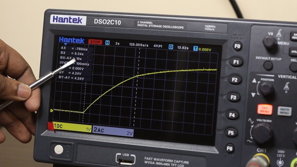
I have calculated from the online calculator, that 470K resistor and 33uf capacitor has a time constant of around 15sec. To charge the capacitor to 4.2V the constellation takes around 10 seconds. As you have seen on the oscilloscope in the previous image.
The capacitor and the resistor are connected with the non-inverting input of the op-amp. When the capacitor is charged at 4.2V the output of this op-amp will turn on because the op-amp’s reference voltage is already set at 4.2V.

So, If I explain everything at once for the ‘Low’ water level detection circuit then the system works like the following: when the water level drops beneath the ‘Sensor 3’ the output of the opamp U1.2 will deactivate which leads to activate the output of the ‘Not Gate’ constellation that directly activates the charging process of the capacitor C2. As the opamp U1.4 output is inverted because of another transistor ‘Not Gate’ configuration until the capacitor reaches around 4.2V, the op-amp stays deactivated which leads to this inverting output being activated, and ultimately the buzzer stays activated. Meanwhile, when the water level drops to a certain degree the output here only stays activated just for 7-10 seconds.
The timer of the ‘High’ water level detection section is almost similarly configured. As the water level touches the sensor, the output of the U1.1 op-amp activates and that gradually turns on the charging process of the capacitor C1. Until the capacitor charges to 4.2V the output of the ‘Not gate’ gets activated. After 7 to 10 seconds when the capacitor charges to 4.2V the op-amp U1.3 activate which gradually deactivates the ‘Not gate’ output as well the buzzer.

Last but not least are these resistors whose job is just to prevent the IC pins from floating.

When I am quite happy with the design I assembled the circuit on the breadboard and it works really great. So, it’s time to think of something permanent.

Water Level Detection Circuit Assembling
After taking out all the components from the breadboard, I have soldered them one another on a piece of perf board. The wiring is mostly done with the excess legs of the components and in some cases, flexible wires have come in extremely handy. Also, I haven’t soldered the IC into the perf board directly I have used sockets so that if anything goes wrong with IC in the future we can replace it.

This brings me to a point where I should say, without testing all the voltages in the IC pins don’t insert the IC into its socket. So, without inserting the IC I have hooked up the power and done the voltage calibration on the voltage divider to perfectly spit 4.2V.

After double-checking the supply voltage between the VCC and GND pin of the IC I can insert the IC into its socket.


Ok, now I can insert the IC into its socket and start testing. So, I have dipped the positive wire to the very bottom of a bowl. Set the low water level sensing wire at a little bit of height from the bottom and finally the water full indication wire at the top of the bowl. When the bowl is empty the buzzer is rapidly beeping for 7 to 10 sec. If we pour water in the middle of the beeping the beep stops and no sound occurs until the water touches the max water level sensing wire. At this level, the second buzzer starts buzzing and stops after around 10 seconds. Perfect.
Power Supply For the Water Level Sensor
As soon as the circuit is performing well so it’s time to think of a suitable power supply that I could also use inside my water cooler. Without increasing my thoughts to the space, I have picked up this 5V 0.7A power adapter of an old mobile phone. By stepping up the voltage at 12V with an MT3608 boost converter I could easily power up the circuit.

It works without any issues.
Pump 6 Minutes Timer
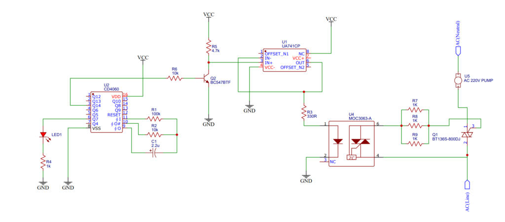
So, the water level sensor is done. Now we need to set up a timer for the pump so that it can turn on/off in every 6 Minutes interval. This is the circuit I came up with.
The CD4060 decade counter with the combination of a few complementary components I can achieve what I am looking for. I am not explaining the circuit right now but one thing I have to mention to operate the cooler pump I need to use a relay however in this case a simple mechanical relay wouldn’t do the job because of the high inrush current of the pump the terminals inside the relay get fused with each other and start malfunctions. So, I will have to use the circuit shown in the diagram below. It is an electric relay aka Solid State Relay – no mechanical components either. I am not going into detail right now that would be the subject for another time.
Enclosure and its Design and Assembly
So, there we have it. The circuit is done. What we need to do is just assemble everything. Ofcourse using such a naked circuit inside the air water cooler isn’t a good idea so I have designed a 3D-printed case with 3 mounting holes so that I can slide zip ties through them to hold the case in the right place. I have also designed another small one for the power supply and the boost converter.

After 3D printing, I have mounted the circuit inside the housing, slid the zip ties beneath it, and tied it with the body of the cooler. The power supply is also mounted with zip ties.

After connecting the power and sensor wires, and pump with the corresponding wires it’s time for a test run.

It ofcourse works. The pump is turn on/off in every 6 minutes, water level indicator works but after a few days of usage I have noticed a problem.
Troubleshoot the Design Error
Setting up all the sensors with a PVC pipe is actually a terrible idea that I have realized after a few days of usage. Just think of it I filled the tank and one by one all the sensors and the PVC pipe is drowned. After a while, when the water level is dropping sensors are exposing to air but the PVC pipe isn’t Immediately dried out. It holds the water which leads to current flow through the water and finally through the sensors and circuit and that causes error and malfunctioning. You can understand it better from the video above.

However, that might not be the case for the water ‘Full’ detection sensor because it is set way above from the common VCC aka Sensor 1. So, it gets the time to release the water but the ‘Low’ water level detection sensor creates problem. The PVC pipe in that section might not get sufficient time to dry out. so when water goes below the sensor it will not be detected immediately until this section is completely dried out.

To solve this problem, either I have to use such a material that doesn’t get wet with water or separate the low water detection sensor aks Sensor 3 from the PVC pipe and set it separately which actually I did at least for now.

AC High Voltage Wiring
The AC wiring is pretty straightforward the circuit is directly powered from the AC mains inside the cooler. No switch and nothing in between. When I plug-in the cooler it will Immediately turn on. This is the simplified diagram. The pump is in the series with the circuit as shown in the scheme below.

If you’re going to replicate such a design please be careful AC mains voltage is lethal and extremely dangerous. If you have no idea what you are doing maintain the distance from the AC mains voltages.
Conclusion
So, there we have it. The water level detection circuit detects the water level ‘High’ or ‘Low’ and sounds an alarm in both states for 7 – 10 seconds. A 6 minutes timer turns ‘on/off’ the pump of the cooler. So, I have what I was initially looking for and I am really happy with the results what are your thoughts? Let me know in the comment section below. If you like this article consider supporting me by sharing the video and the article with your friends. Thanks for visiting.
Your point of view caught my eye and was very interesting. Thanks. I have a question for you.